1 lcd硬件操作原理
Lcd显示的过程如下:
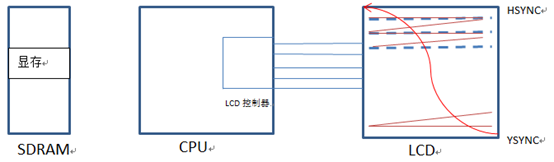
- 从显存中输出显示颜色的数据,在屏幕左上角的第一个点开始显示,每间隔一个像素时钟VCLK,向右移动一个点,当移到最右边时,会根据水平同步信号HSYNC跳到下一行的最左边;
- 又重复步骤1的操作,直到显示到右下角最后一个点为止,这时根据垂直同步信号YSYNC,又跳回到左上角第一个点开始下一帧图片的显示。
2 编写驱动
在上一章节结尾已经理出了lcd驱动程序的大致流程。首先来实现入口函数lcd_init函数。
- 分配一个fb_info空间;
- 对fb_info指向的结构体进行配置;
- 设置可变参数;
- 设置固定参数;
- 设置fops;
-
- 设置其他参数。
- 硬件相关的配置;
- 设置lcd相关的引脚;
- 设置lcd控制器的寄存器;
- 设置显存,并将显存的地址通知到lcd控制器;
- 开启lcd,lcd控制器以及背光。
-
- 注册framebuffer。
出口函数lcd_exit主要实现对资源的释放,具体操作如下:
- 卸载framebuffer;
- 关闭lcd控制器,背光;
- 释放显存空间;
- 解除所有io资源的映射;
- 释放申请的fb_info空间。
详细的代码如下所示。
- #include <linux/module.h>
- #include <linux/kernel.h>
- #include <linux/errno.h>
- #include <linux/string.h>
- #include <linux/mm.h>
- #include <linux/slab.h>
- #include <linux/delay.h>
- #include <linux/fb.h>
- #include <linux/init.h>
- #include <linux/dma-mapping.h>
- #include <linux/interrupt.h>
- #include <linux/workqueue.h>
- #include <linux/wait.h>
- #include <linux/platform_device.h>
- #include <linux/clk.h>
-
- #include <asm/io.h>
- #include <asm/uaccess.h>
- #include <asm/div64.h>
-
- #include <asm/mach/map.h>
- #include <asm/arch/regs-lcd.h>
- #include <asm/arch/regs-gpio.h>
- #include <asm/arch/fb.h>
-
- static volatile unsigned long *gpbcon;
- static volatile unsigned long *gpbdat;
- static volatile unsigned long *gpccon;
- static volatile unsigned long *gpdcon;
- static volatile unsigned long *gpgcon;
- static u32 pseudo_pal[16];
-
- struct lcd_regs{
- unsigned long lcdcon1;
- unsigned long lcdcon2;
- unsigned long lcdcon3;
- unsigned long lcdcon4;
- unsigned long lcdcon5;
- unsigned long lcdsaddr1;
- unsigned long lcdsaddr2;
- unsigned long lcdsaddr3;
- unsigned long redlut;
- unsigned long greenlut;
- unsigned long bluelut;
- unsigned long reserved[9];
- unsigned long dithmode;
- unsigned long tpal;
- unsigned long lcdintpnd;
- unsigned long lcdsrcpnd;
- unsigned long lcdintmask;
- unsigned long tconsel;
- };
- static volatile struct lcd_regs *lcdregs;
-
- static struct fb_info *s3cxx_lcd;
- static int s3cfb_setcolreg(unsigned regno,
- unsigned red, unsigned green, unsigned blue,
- unsigned transp, struct fb_info *info);
-
- static struct fb_ops s3c_lcdfb_ops = {
- .owner = THIS_MODULE,
- .fb_setcolreg = s3cfb_setcolreg,
- .fb_fillrect = cfb_fillrect,
- .fb_copyarea = cfb_copyarea,
- .fb_imageblit = cfb_imageblit,
- };
-
- static inline unsigned int chan_to_field(unsigned int chan, struct fb_bitfield *bf)
- {
- chan &= 0xffff;
- chan >>= 16 - bf->length;
- return chan << bf->offset;
- }
-
- static int s3cfb_setcolreg(unsigned regno,
- unsigned red, unsigned green, unsigned blue,
- unsigned transp, struct fb_info *info)
- {
- unsigned int val;
-
- if(regno > 16)
- return 1;
-
- /* 用red green blue三原色构造出val */
- val = chan_to_field(red, &info->var.red);
- val |= chan_to_field(green, &info->var.green);
- val |= chan_to_field(blue, &info->var.blue);
-
- pseudo_pal[regno] = val;
- return 0;
- }
-
- static int lcd_init(void)
- {
- /* 1、分配一个fb_info空间 */
- s3cxx_lcd = framebuffer_alloc(0, NULL);
-
- /* 2、配置 */
- /* 2.1、设置可变参数 */
- s3cxx_lcd->var.xres = 480;
- s3cxx_lcd->var.yres = 272;
- s3cxx_lcd->var.xres_virtual = 480;
- s3cxx_lcd->var.yres_virtual = 272;
- s3cxx_lcd->var.bits_per_pixel = 16;
- /* RGB:565 */
- s3cxx_lcd->var.red.offset = 11;
- s3cxx_lcd->var.red.length = 5;
- s3cxx_lcd->var.green.offset = 5;
- s3cxx_lcd->var.green.length = 6;
- s3cxx_lcd->var.blue.offset = 0;
- s3cxx_lcd->var.blue.length = 5;
- s3cxx_lcd->var.activate = FB_ACTIVATE_NOW;
-
- /* 2.2、设置固定参数 */
- strcpy(s3cxx_lcd->fix.id, "mylcd");
- s3cxx_lcd->fix.smem_len = 480*272*16/8;
- s3cxx_lcd->fix.type = FB_TYPE_PACKED_PIXELS;
- s3cxx_lcd->fix.visual = FB_VISUAL_TRUECOLOR;
- s3cxx_lcd->fix.line_length = 480*2;
-
- /* 2.3、设置fbops */
- s3cxx_lcd->fbops = &s3c_lcdfb_ops;
- /* 2.4、设置其他参数 */
- s3cxx_lcd->pseudo_palette = pseudo_pal;
- s3cxx_lcd->screen_size = 480*272*16/8;
-
- /* 3、硬件相关的操作 */
- /* 3.1、设置lcd的引脚 */
- gpbcon = ioremap(0x56000010, 8);
- gpbdat = gpbcon + 1;
- gpccon = ioremap(0x56000020, 4);
- gpdcon = ioremap(0x56000030, 4);
- gpgcon = ioremap(0x56000060, 4);
-
- /* GPIOc管脚用于VD[7:0]、LCD_LPCREVB、LCD_LPCREV、 LCD_LPCOE、VM、VFRAME、VLINE、VCLK、LEND */
- *gpccon = 0Xaaaaaaaa;
- /*GPIOd管脚用于VD[23:8] */
- *gpdcon = 0Xaaaaaaaa;
- /* GPIOB0管脚设为输出引脚 */
- *gpbcon &= ~0x03;
- *gpbcon |= 0x01;
- *gpbdat &= ~0x01;
- /*gpiog4管脚用于LCD_PWRDN */
- *gpgcon |= (3<<8);
-
- /* 3.2、设置lcd控制器的寄存器 */
- lcdregs = ioremap(0X4D000000, sizeof(struct lcd_regs));
- /* lcdcon1
- * bit[17:8] vclk = hclk /[(clkval + 1)*2]
- 10000000Hz(100nS) = 100000000/[(clkval + 1)*2]
- clkval = 4
- * bit[6:5] 11 = TFT LCD panel
- * bit[4:1] 1100 = 16 bpp for TFT
- * bit[0] 0 = Disable the video output and the LCD control signal
- */
- lcdregs->lcdcon1 = (4 << 8)| (3 << 5) | (0x0c << 1) ;
- /*
- * lcdcon2 垂直方向的时间参数
- * bit[31:24] VBPD VSYNC之后多久才能发出第一行数据
- * LCD手册上 T0-T2-T1 = VBPD + 1 = 4;
- VBPD=3
- * bit[23:14] LINEVAL 显示的行数 320 = LINEVAL + 1;
- * LINEVAL = 319;
- * bit[13:6] VFPD 最有一行数据发出多久后,再发出VSYNC
- * VFPD T2-T5 = VFPD + 1;
- * VFPD=1;
- * bit[5:0] VSPW VSYNC信号的脉冲宽度
- * VSPW + 1 = T1 = 1
- * VSPW = 0;
- */
- lcdregs->lcdcon2 = (1 << 24) | (271 << 14) | (1 << 6) |(9);
- /*
- * lcdcon3 水平方向的时间参数
- * bit[25:19] HBPD HSYNC之后多久才能发出第一行数据
- * LCD手册上 T6-T8-T7 = HBPD + 1 =273-251-5=17;
- HBPD=17
- * bit[18:8] HOZVAL 显示的列数 240 = HOZVAL + 1;
- * LINEVAL = 239;
- * bit[7:0] HFPD 最后一行的最后一个数据发出多久后,再发出HSYNC
- * VFPD T8-T11 = 251-240=11=VFPD+1;
- * VFPD=10;
- */
- lcdregs->lcdcon3 = (1 << 19) | (479 << 8) | (1 << 0);
- /*
- * lcdcon4 水平方向的时间参数
- * bit[7:0] HSPW HSYNC信号的脉冲宽度
- * HSPW T7 = HSPW+1 = 5;
- * HSPW=4;
- */
- lcdregs->lcdcon4 = (40 << 0);
- /*
- * 信号的极性
- * bit[11] 1 = 5:6:5 Format
- * bit[10] 0 = The video data is fetched at VCLK falling edge
- * bit[9] This bit indicates the VLINE/HSYNC pulse polarity. 1 = Inverted
- * bit[8] This bit indicates the VFRAME/VSYNC pulse polarity. 1 = Inverted
- * bit[6] This bit indicates the VDEN signal polarity. 0 = Normal
- * bit[3] PWREN LCD_PWREN output signal enable/disable.0 = Disable PWREN signal 1 = Enable PWREN signal
- * bit[1] BSWP =0
- * bit[0] HWSWP = 1 参照2440手册
- */
- lcdregs->lcdcon5 = (1 << 11) | (0 << 10) | (1 << 9) | (1 << 8) | (1 << 0);
-
- /* 3.3、设置显存,并将显存的地址通知到lcd控制器*/
- s3cxx_lcd->screen_base = dma_alloc_writecombine(NULL, s3cxx_lcd->fix.smem_len, &s3cxx_lcd->fix.smem_start, GFP_KERNEL);
- lcdregs->lcdsaddr1 = (s3cxx_lcd->fix.smem_start >> 1) &~(3<<30);
- lcdregs->lcdsaddr2 = ((s3cxx_lcd->fix.smem_start + s3cxx_lcd->fix.smem_len) >> 1) & 0x1fffff;
- lcdregs->lcdsaddr3 = (480*16/16); /* 一行的长度(单位:2字节) */
-
- lcdregs->lcdcon1 |= (1<<0); /* 使能LCD控制器 */
- lcdregs->lcdcon5 |= (1<<3); /* 使能lcd */
- *gpbdat |= 1; /*输出高电平,打开背光 */
-
- //s3cxx_lcd->fix.smem_start /* 显存的物理地址 */
- /* 4、注册 */
- register_framebuffer(s3cxx_lcd);
-
- return 0;
- }
-
-
- static void lcd_exit()
- {
- unregister_framebuffer(s3cxx_lcd);
- lcdregs->lcdcon1 &= ~(1<<0);
- *gpbdat &= ~1;
- dma_free_writecombine(NULL, s3cxx_lcd->fix.smem_len, s3cxx_lcd->screen_base, s3cxx_lcd->fix.smem_start);
-
- iounmap(lcdregs);
- iounmap(gpbcon);
- iounmap(gpccon);
- iounmap(gpdcon);
- iounmap(gpgcon);
- framebuffer_release(s3cxx_lcd);
- }
-
-
- module_init(lcd_init);
- module_exit(lcd_exit);
-
- MODULE_LICENSE("GPL");
3 编译调试
- 去掉内核中原有的lcd驱动
使用make menuconfig命令,对内核重新配置。

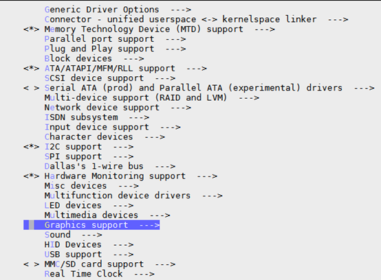
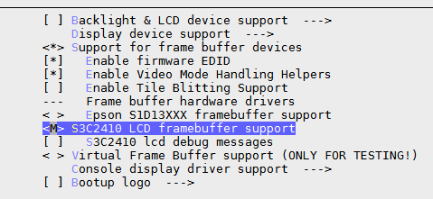
如上图所示,由->Device Drivers进入,选择->Graphics support,最终将sc2410 lcd framebuffer support设置成M,作为模块编译。因为在fb_ops结构体中,cfb_fillrect、cfb_copyarea、cfb_imageblit三个模块被调用了,所以需要将sc2410 lcd framebuffer作为模块进行编译,方便我们后面对这三个模块进行挂载。

- 对内核设置完成后,使用make uImage命令编译内核,使用make modules命令编译模块。编译结束后,将uImage和cfbfillrect.ko、cfbcopyarea.ko、cfbimageblit.ko分别拷贝到可被NFS挂接的目录下/work/nfs_root/...。
- 通过nfs服务,使用新的uImage启动系统。
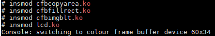
- 装载cfbfillrect.ko、cfbcopyarea.ko、cfbimageblit.ko和lcd.ko驱动模块。
- 测试。
使用echo hello > /dev/tty1命令,将hello输出到lcd终端。会发现lcd屏幕上打印出"hello"字符。
使用cat lcd.ko > /dev/fb0命令,将lcd.ko的内容显示到lcd上。这里显示的是花屏的效果。
视频中使用的是3.5寸的lcd屏,这里需要将对应的参数修改成4.3寸屏的,才能看到正确的实验现象。